Installation Guidelines
1. Plan
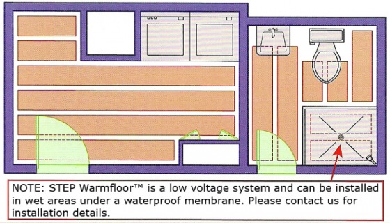
- Design the system and make a layout. Elements should be placed in open areas away from conductive materials, plumbing and fixed fittings.
- Proper thermal insulation with no voids is required in the floor and by the perimeter.
- Installation should conform to local building codes, ordinances and trade practices.
2. Install
- Roll the element out on the floor and cut to length according to layout. Lay the element strips side by side following the recommended spacing.
- The element can be attached to the subfloor using the following alternatives:
3/8 inch. If the staple hits a bus braid, cut the element, splice and
seal properly.
- Use only approved tape and apply perpendicular to the direction of
element.
- Cement mortar or latex-modified mortar can be used for leveling or
when installing tile or underlayment.
NOTE: Do NOT use non-approved tape or adhesive based products (premix thin-set, primer, leveler or equivalent) to adhere the element. Avoid contact between elements. Do NOT puncture the bus braids.
3. Connect
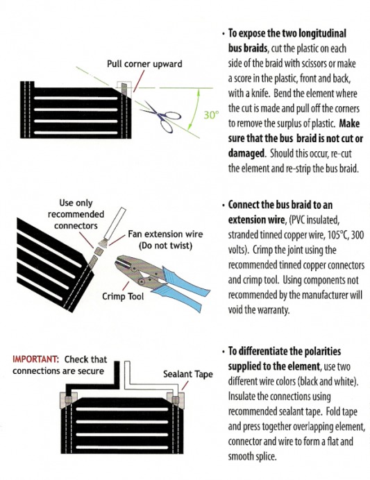
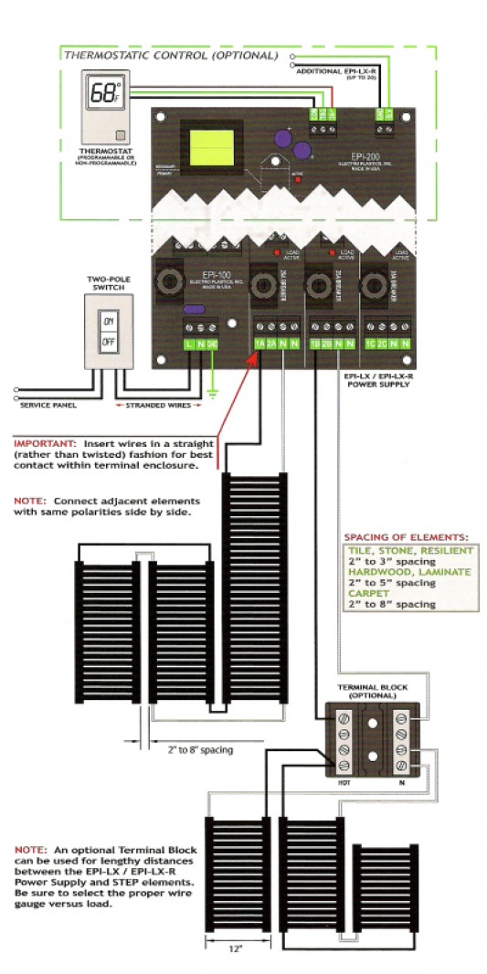
- Connect extension wires to the elements according to the drawings and electrical diagram. Determine wire gauge versus load.
- Route the wires flat on the floor, up or through the wall in conduits, under the baseboard or below the subfloor. Connect wires in parallel to the 24 volt EPI-LX / EPI-LX-R power supply. Use only stranded tinned copper wires and do not twist ends when connecting to the interface board in power supply.
- Distribute the load evenly. The maximum load per circuit is 450 watts.
- The EPI-LX / EPI-LX-R power supply must be installed in a well ventilated area and wired in accordance with the National Electrical Code. Place the power supply in a way that it does not vibrate and give resonance in the building structure.
- Connect the line voltage to two-pole on/off switch. Use stranded wires from the switch to the EPI-LX / EPI-LX-R power supply. For control options, see the STEP Handbook (please contact us).
- To simplify wiring and circuit breakers, use 230 volts. For certain areas, NEC requires AFCI circuit breakers on 120 volt systems.
- The heating elements must be measured and amps noted by a certified electrician before being covered.
Connections
Wiring Diagram
4. Cover
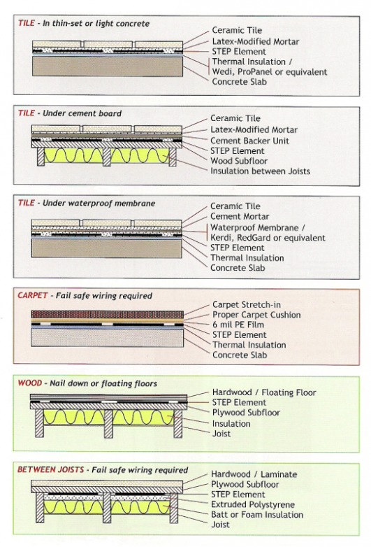
- Level the floor using proper mortar, underlayment or cement backer boards. Do NOT place a conductive material or aggressive adhesive in direct contact with the heating elements.
- To be efficient the heating elements have to be in direct contact with the finished flooring, with no air gaps. In bathrooms, showers, and wet areas, the heating elements should be installed under a waterproof membrane.
- The heating elements provide a safe and even low temperature and can go under most floor coverings. Follow manufacturer's instructions.
Flooring Options and Installation
Thermal Insulation Guidelines
- With radiant heating, it is important to have insulation under the heating elements and on the slab perimeter.
- A higher R-value is required under the heating elements as opposed to over with a ratio of 4:1.
- Consult insulation manufacturer for deflection/load characteristics, and check that the product and installation procedure is approved for the application.
Please email us with any questions:
[email protected]


